

Sometimes little wins give you disproportionate satisfaction.
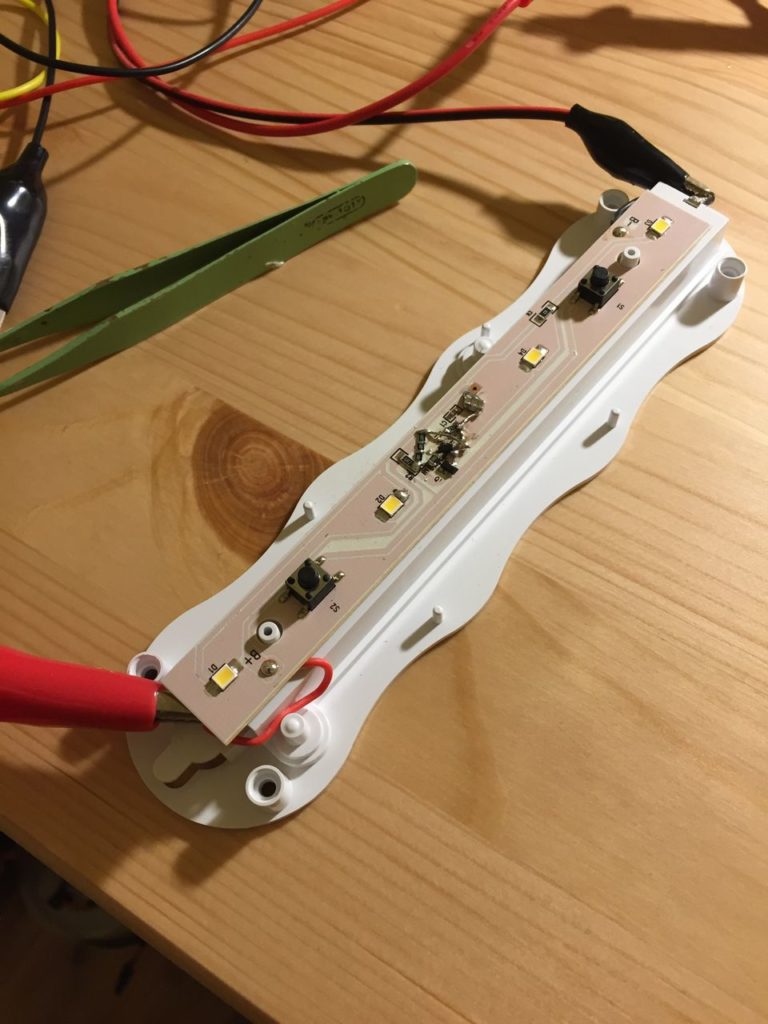
I bought a battery-powered LED light from a local hardware store. It cost 10 bucks and is surprisingly decent quality, using 3 x AAAs. Pushing the front bezel turns it on, pushing it again turns it off. I bought it for the enclave under the stairs where the wine lives. Problem is, I was confident that at some stage we’d would forget to turn it off again and come back to a non-functional light. That happened ahead of schedule, the first batteries lasted about a week. Righto then, we’ll fix that.
Looking at the circuit, the pushbutton grounded one pin of a small 5-pin IC which then was connected via a transistor of some sort to the lights. The IC was just a toggle (flip flop maybe?) and probing the circuit indicated the transistor was a PNP BJT.
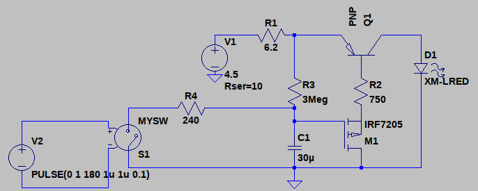
What this circuit needed was a one-shot time delay. A 555 timer would be ideal but takes 24 transistors to do a simple job. And besides, it’s Sunday and I can’t be bothered going to the store. What’d work, and be really simple, is a P-channel MOSFET delay circuit. Use the button to yank the gate low, PMOS pulls base current out of the BJT which turns it on, use an RC circuit to pull the gate high again, and you’re done. Get rid of the flip-floppy thing, we don’t need it.
A parts scrounge produced a suitable PMOS device, some 10uF capacitors, and some 1Meg resistors. A little bit of LTSPICEing suggested that 3 capacitors in parallel and 3 resistors in series gave the right timing:
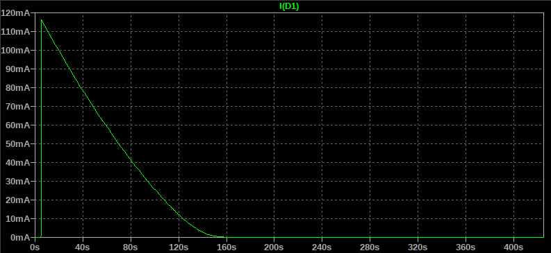
Cool, about a minute before the light dims noticeably (our eyes are logarithmic) and it’ll be well and truly off after 3 minutes (the current drops to nanoAmps after a few minutes, less than the self-discharge rate of the batteries).
Let’s fire up the 25 year old soldering iron to make it happen:
A closer look at this monstrosity:
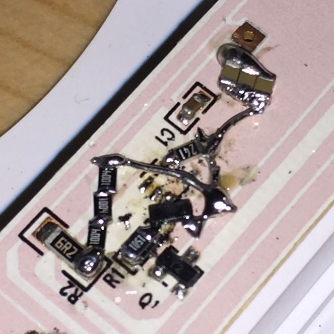
It ain’t pretty, but nobody’s ever gonna see… oops.
To the left we have a 6.2 ohm resistor (connected to the batteries) for limiting the LED current, and my 3 x 1Meg resistors in series. The 3 resistors charge 3 x 10uF ceramic capacitors (top), which gently tug on the gate of the P-channel MOSFET (centre). The pushbutton switches ground the capacitors via a 240 Ohm resistor (to limit current). The MOSFET, via 2 x 1.5K parallel resistors (750 Ohms) pulls some base current out of the PNP BJT (Q1) to turn it on. Let there be light! After minute or two the capacitors have charged through 3 MegaOhms of resistance and gradually turn the lights off again.
If you’re still head-scratching you have to push the bezel again. Serves you right.
Let there be wine!
![]()