

Late in 2019 I heard of an upcoming project by SpaceAustralia to home brew your own radio-telescope, with the objective of peering at the Milky Way. Previously only the domain of scientists with very nice radio dishes, the reducing cost of entry has now put it in range of the hobbyist so it seemed like a cool thing to try.
Any given Hydrogen atom floating in space emits a little pulse of radio energy every 10 million years or so, at 1420.4MHz – Wiki. By measuring the strength of the radio wave emissions and the Doppler shift, you can get an idea of the quantity and direction of the Hydrogen.
Space Australia’s recommended build was a pyramidal horn antenna, but in the interests of doing something a little different I thought about a Helical antenna. This should be a little easier to build, and the fancy antenna simulation software I have access to at work suggested it might be possible to use a Helical antenna for this task. The biggest challenge is the Hydrogen Line signal is very weak – so weak that thermal noise from the Earth is much noisier (and an antenna needs to be very directional).
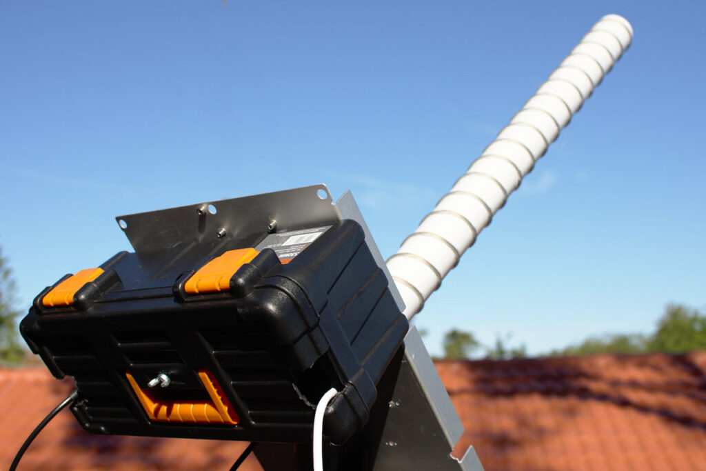
I ended up with a build consisting of an aluminium backplate, a length of 50mm PVC pipe, and some speaker wire wound 20 turns up the outside and hot-glued in place. On the back was a cheap plastic tool box to give some protection to the electronics.
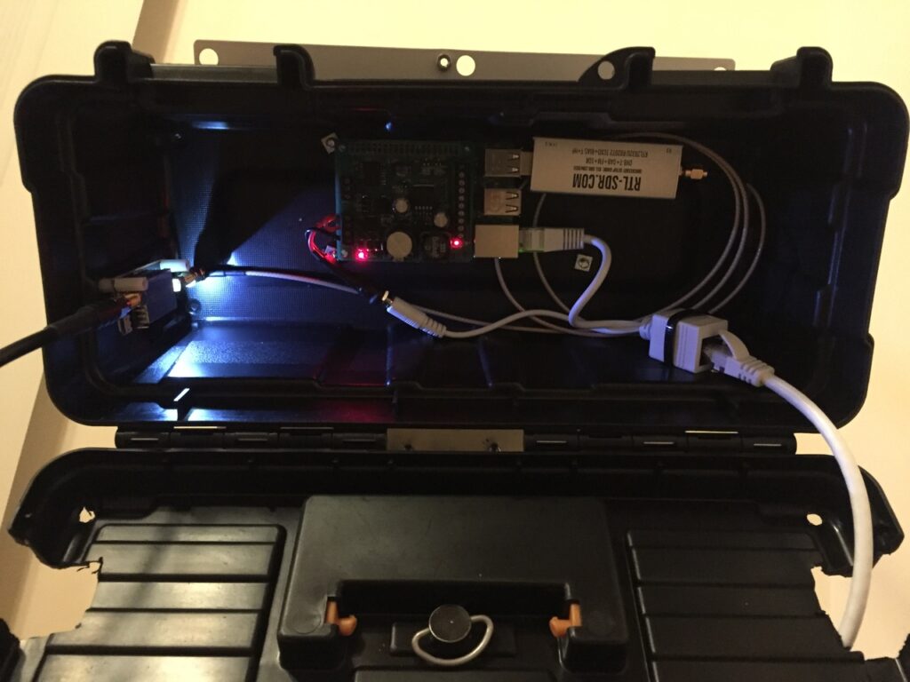
Off the back of the antenna, the preamp is a NooElec SAWBird+ H1, which is 2 LNA’s sandwiching a narrowband filter. This preamp also has a switchable 50 Ohm load, for taking noise calibration measurements. The output is fed to an RTL-SDR.com dongle, with streaming data from the dongle piped through the Raspberry Pi by rtl_tcp and ultimately ending up on my fileserver.
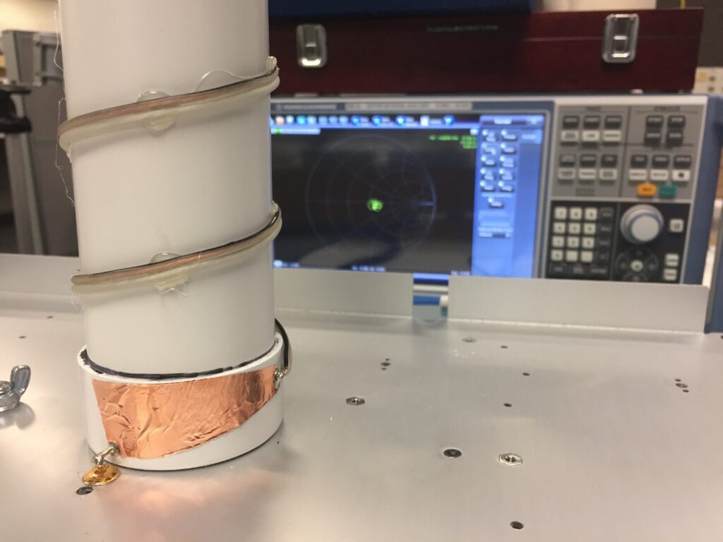
Helical antennas require some impedance matching, which the fancy measuring equipment I have access to at work confirmed was doing the right job. A triangular piece of copper tape converts the 50 ohm feedpoint into the ~120 Ohm characteristic impedance of the antenna.
The rest of the measurements looked good too (helicals are broadband impedance-wise, but their pattern degrades quickly away from design frequency):
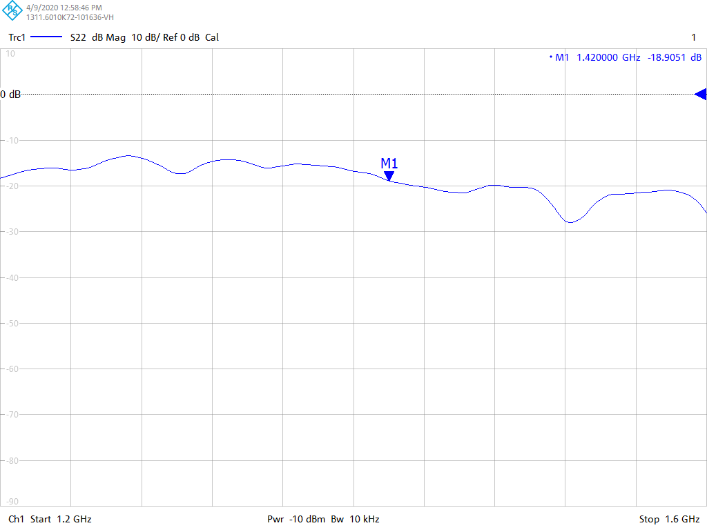
Reflection coefficient 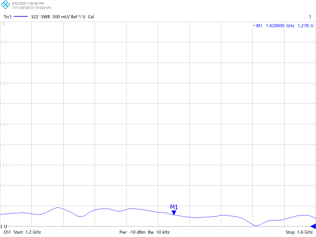
SWR 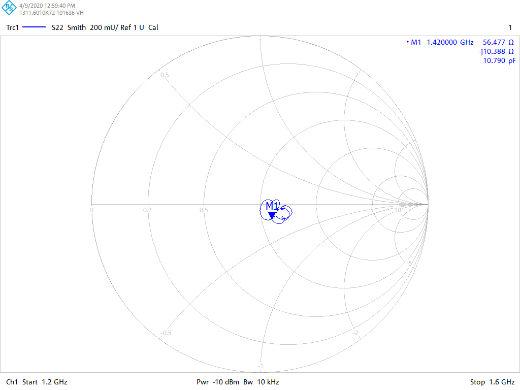
Smith chart
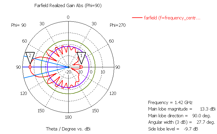
Simulated results suggest a fairly clean pattern. In the below plot, the purple circle is 15dB below the main lobe. 20dB would have guaranteed that a hot Earth wouldn’t degrade my measurements, this design does get there but only directly behind the antenna. I can expect to see some noise degradation with this build unless my antenna points directly upwards.
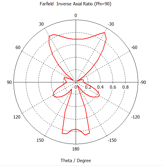
At some point, simulations churned out this interesting-looking plot:
Unfortunately my current location doesn’t have an unobstructed sky view, the best I could do from our balcony was pointing at 45 degrees elevation into a clear patch of sky. Trees, houses, and our own roof conspired to inject noise from the sides but as a system check it was worth trying out. With the fortune of good weather, the antenna stayed out there for 6 full days. In the end this amounted to 1.5TB of raw data.
After much fiddling with the data, there it was! A quite noticeable bump that appears when the Milky Way core (Sagittarius) passes through the antenna beam, and a smaller bump at lower frequency when the opposite direction (Orion) passes through 12 hours later:
The setup also did look quite photogenic at night:
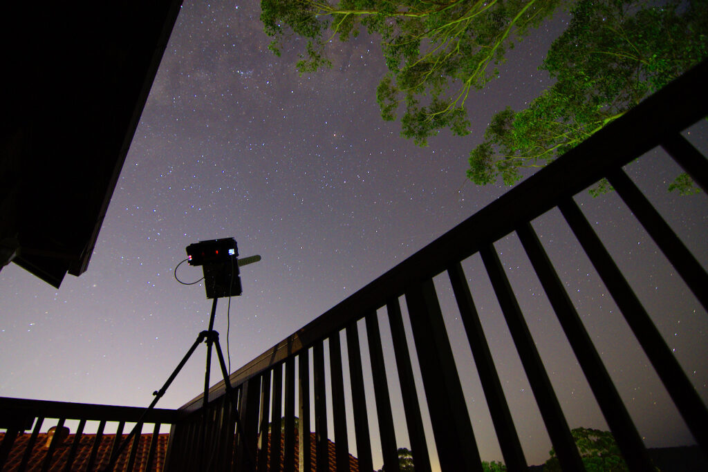
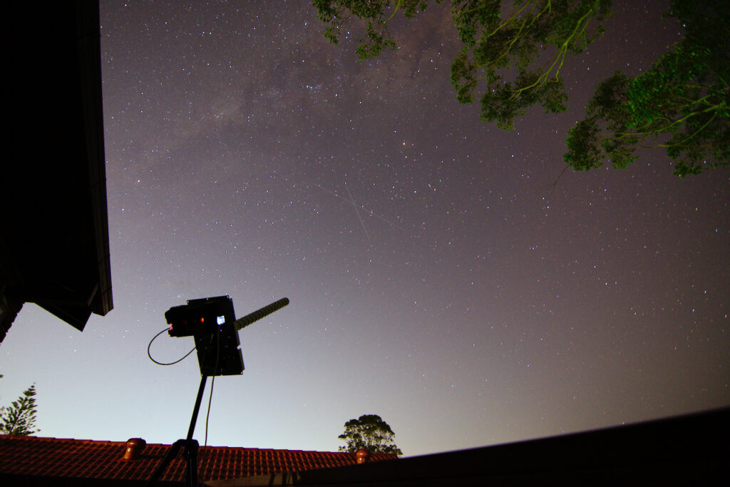
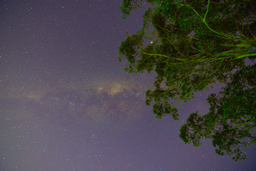
![]()