
Last Xmas I bought myself a quadcopter, and have had fun flying it. Unfortunately after an “attack of dog” (a friend’s dog was trying to be helpful by retrieving the quad any time it landed) one of the motor wires broke. Rejoining the wire was a snap, but the quad did not turn on. It just gave a brief flash of its LED before switching off again.
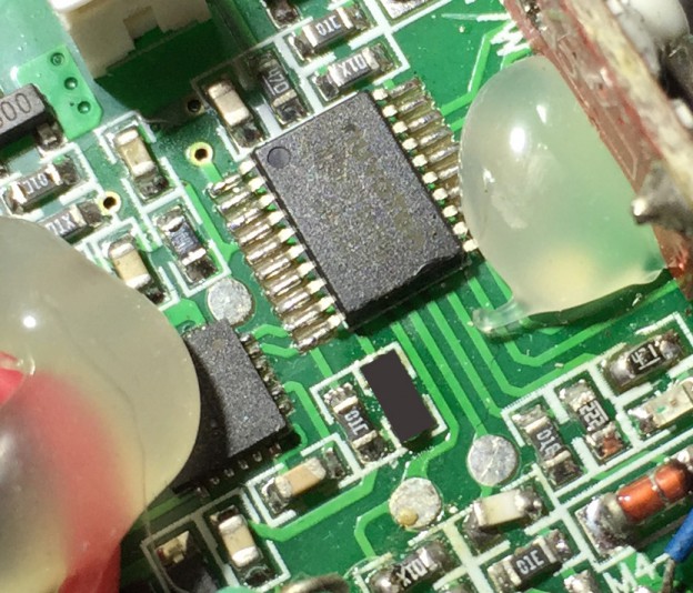
I had a close look at the main board and found a generally shoddy soldering job – look for the upside down resistor! One of the components was also missing (blacked out in the picture). So how to identify and replace this mystery component?

Next to the missing component was what looked like a resistor, but the “J10” marking is non-standard. Probing it with a multimeter indicated 10kOhm resistance. A continuity test of the empty pads showed that one end of the missing component joined to one end of the 10k resistor. The other end went to pin 9 of the IC. The second half of the 10K resistor went to pin 10 of the IC.
The IC is marked Nuvoton N79E814AT20. Part numbers often have a suffix indicating the “package” so shortening the part number often finds the generic “parent” part. In this case a search for Nuvoton N79E814A was fruitful and turned up a datasheet (the T20 suffix means 20 pin TSSOP package). Most of the datasheet is in Simplified Chinese. However, the title says “Nuvotron 8051”. 8051?? This quadcopter is using a microcontroller design dating back to 1980. It’s as old as I am!! The venerable 8051 has kept pace with the modern world though – the original design could execute 1 million instructions per second (MIPS) but recent 8051 variants can execute 450 MIPS. That’s a lot faster than your average Arduino, and I doubt any of the Intel engineers working on it had the slightest idea that some 35 years later their design would be used in a flying toy with pre-programmed acrobatics.
Anyway, enough nostalgia. What I was after was a pinout and hopefully some indication of what each pin did:
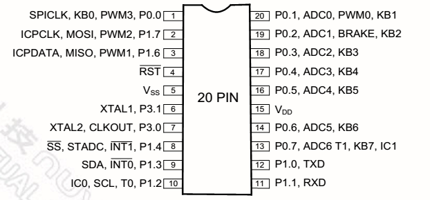
Pin 9 is labelled SDA. The adjacent 10k resistor connects to pin 10, which is SCL. Aha! We seem to have an I2C bus. I2C devices communicate by pulling the data lines down to 0V to indicate a binary ‘0’ or ‘1’. I2C requires a pullup resistor on each data line. That certainly fits what I see on pin 10, so I took an educated guess and figured the missing component was another 10k resistor. I looked through my parts box and the closest I could find was 24k. Two of those in parallel is 12k, close enough! I soldered one on top of another into the empty spot. Bingo!! The quad fired up first time, bound to the transmitter and worked. The micro depends on another chip, most likely an accelerometer – you can see the short traces connecting the two ICs. When the micro couldn’t communicate it just errored out and shut down. So a 1 cent component fixed my quad!
Now, to keep it away from man’s best friend…..
![]()