
The only problem with having several hobbies is when they conflict with each other.
(Surgeon General’s Warning: this is a rambling post so buckle up!)
The Backstory
I’m enthusiastic about amateur radio, being actively involved with my local radio club and I enjoy chatting with friends using our local repeater whilst driving.
I’m also passionate about cars, and my R34 Skyline has an aftermarket ECU which I’ve been learning how to tune. In pursuit of getting more useful (and immediate) feedback on the engine’s operation I installed a Raspberry Pi into my car, powered by my RPi Car Shield. The Pi is now using the official 7″ touchscreen, which is great since it’s a touchscreen, it’s backed by the Raspberry Pi Foundation and it looks really nice. The Pi polls my ECU for data and displays a set of gauges. Great!
The Problem
I was driving along one day after installing it, listening to the local amateur repeater and thinking “this reception is terrible, what’s wrong with our repeater??” (I’m the club’s Repeater Officer so it’s kinda my job to worry about this sort of thing).
I eventually figured out that if my Pi was running, sometimes the reception was dodgy. If the Pi was switched off, I had full reception always.
I should also point out that before the official touchscreen came out I was using a generic LCD panel and had no reception problems. The reception issues only became apparent after installing the official touchscreen.
This was puzzling to me, since the official touchscreen passes Class B EMC certification. Surely it couldn’t be causing the interference, could it? But on the other hand it’s the only ingredient I had recently changed. I had been using a Chinese 7″ display, until it failed and destroyed the Pi’s HDMI port when it went. Cheap rubbish!! (the Chinese display, not the Pi!).
The Investigation
So, let’s get into the nitty gritty.
- The local VHF repeater is sitting on 146.875MHz
- My radio’s S-meter (signal strength meter) sometimes shows a lot of background noise
- The official touchscreen uses DPI with a converter to the RPi’s native DSI interface
- DPI is clocked at 70MHz or so, about half the frequency of my VHF radio (but anything switching will have plenty of harmonic content).
- DPI is known to be problematic in terms of causing interference (but it’s cheap!)
I have access to a Spectrum Analyser through my local club MWRS. These are amazing devices, but carry a hefty price tag. For more information on what a spectrum analyser does check out my club’s recent lecture on the subject.
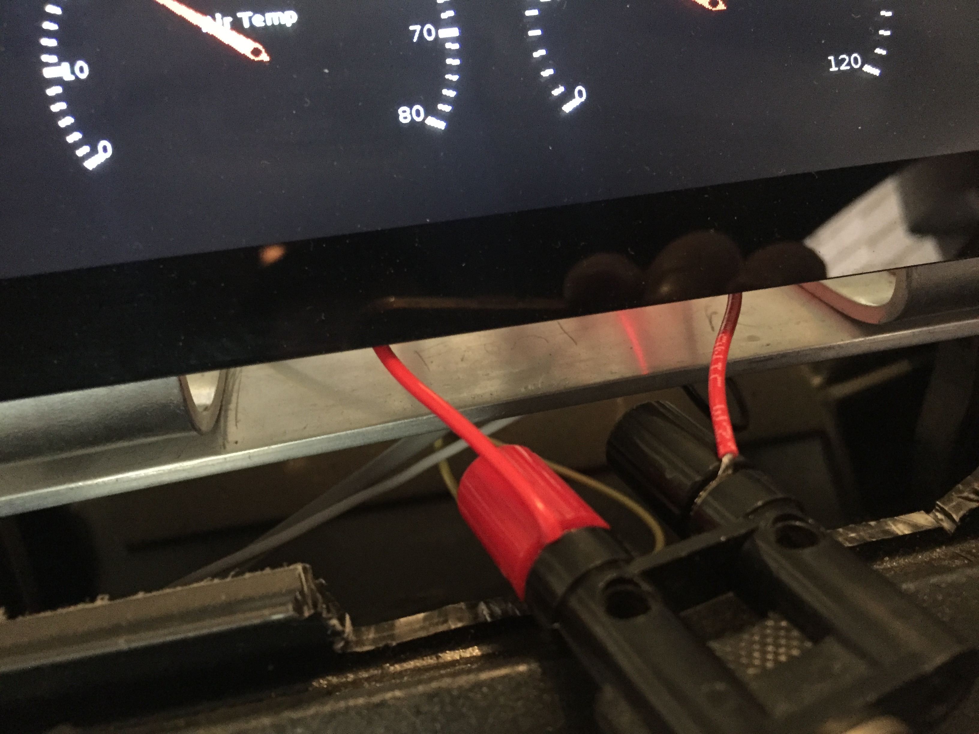
So, first let’s start with the symptom. Here’s my radio’s display when it’s being hammered by interference. The S-meter (bar graph, showing a level of 9) indicates there’s a lot of background noise, and this is without any repeater signal present. Basically anything weaker than the interference will be impossible to hear, it’ll be drowned out. This amount of interference is pretty bad!
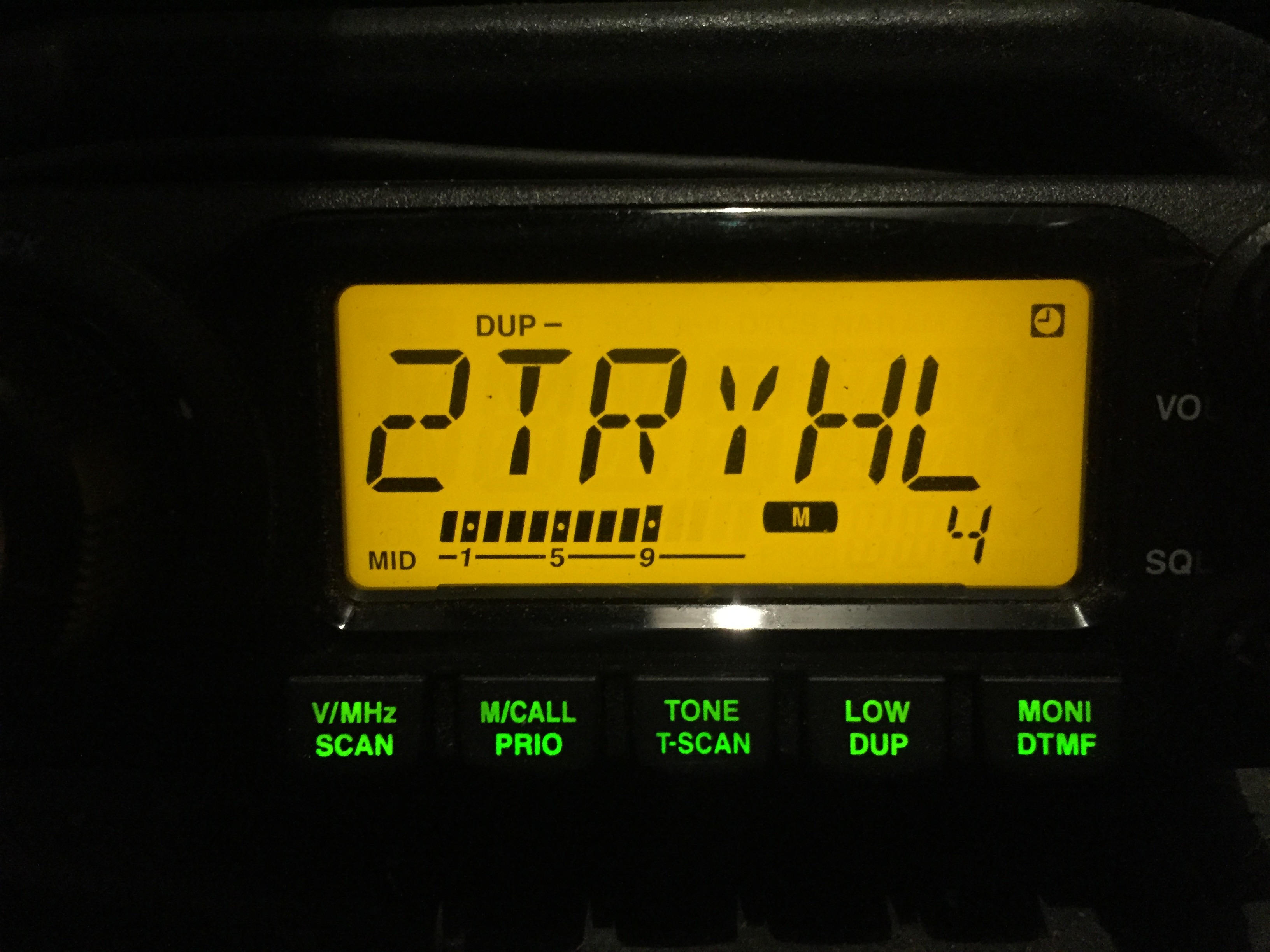
It’s not always as bad as this. Some days I don’t even notice it, but when it’s S9 like this it is quite annoying because I can’t hear the repeater in areas where it should be an easy copy.
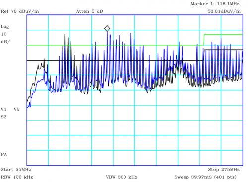
So, what does the Spectrum Analyser show us? I connected it to my antenna on the boot lid to make some measurements of what my radio would normally see:
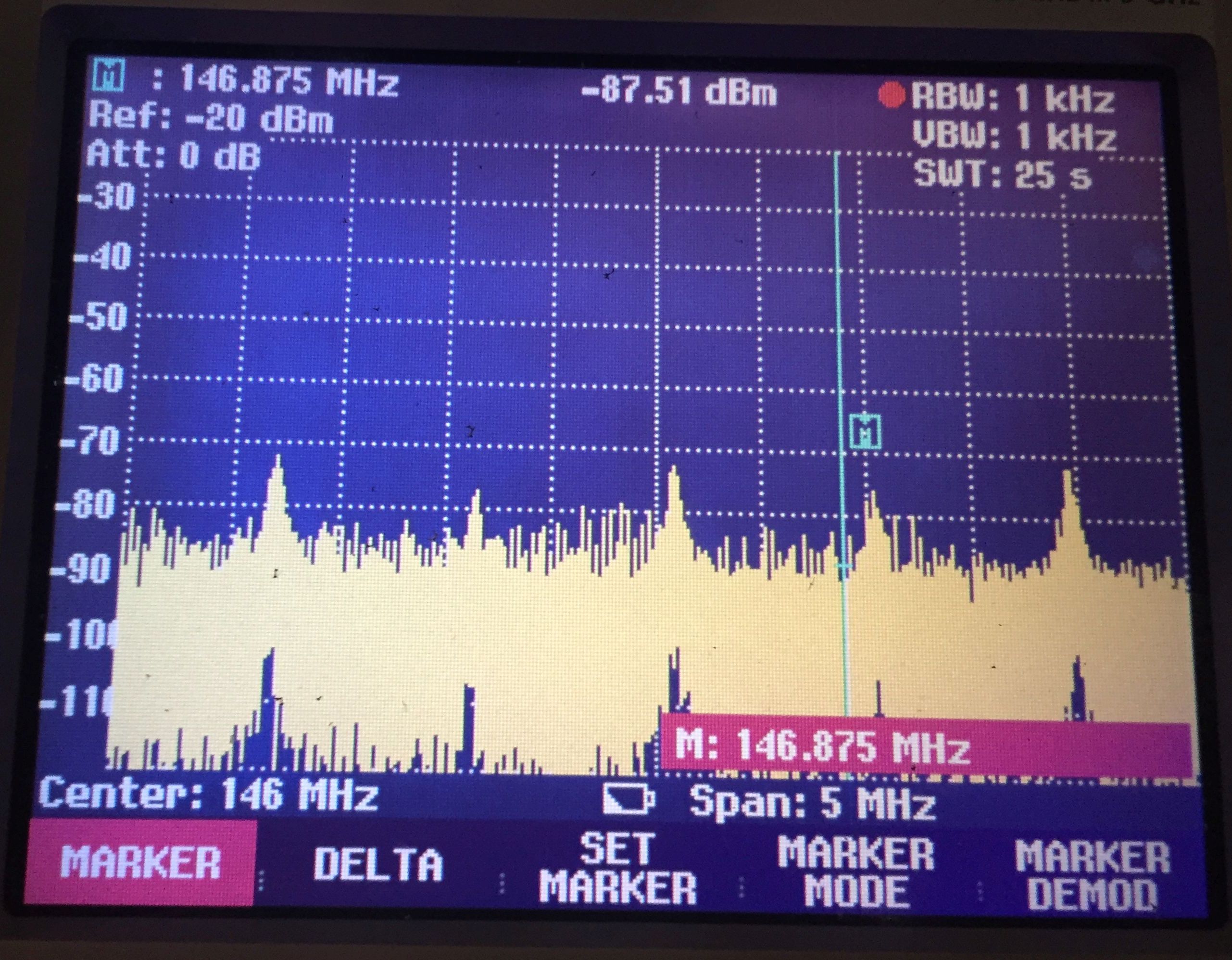
The thick yellow band is background noise, when there is no signal present we are getting samples with a random level between -90 and -120dB. What is a concern are the spikes sticking out of the noise. They come up every 1MHz or so, and the blue line is where the repeater’s signal will be. The spike just to the right of it is the one that causes me grief, as the temperature changes it drifts up and down in frequency and sometimes is right on the repeater’s frequency (causing the radio to show a high level of noise above). These spikes disappear when the Pi’s display is disconnected (ie the Pi running on its own produces no noise but Pi + display is a problem).
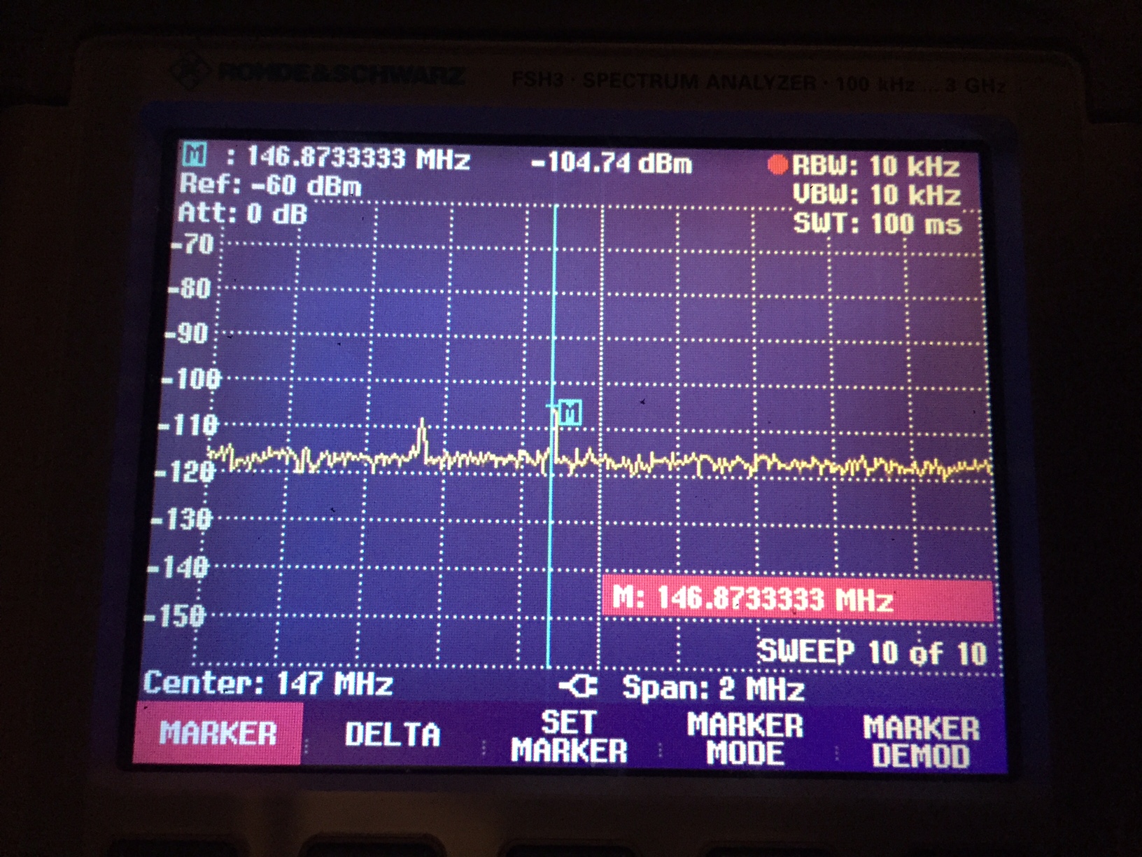
The spectrum analyser has plenty of settings to play with. To clean up the display we can turn on averaging, which has the effect of reducing random noise at the expense of hiding transient signals. But these are relatively constant signals so let’s turn on averaging as it gives us a more easily understood picture.
Here’s the repeater signal I’m trying to listen to (I’m in a weakish signal area, but without the Pi display I have no problems receiving this). Under the blue marker you can see a very narrow spike. Note the signal level up the top of -104.74dBm, and visually it’s about 12dB above the noise floor.
Now, here’s what happens when I power up the Pi display (the repeater has gone quiet but there is plenty else to look at):
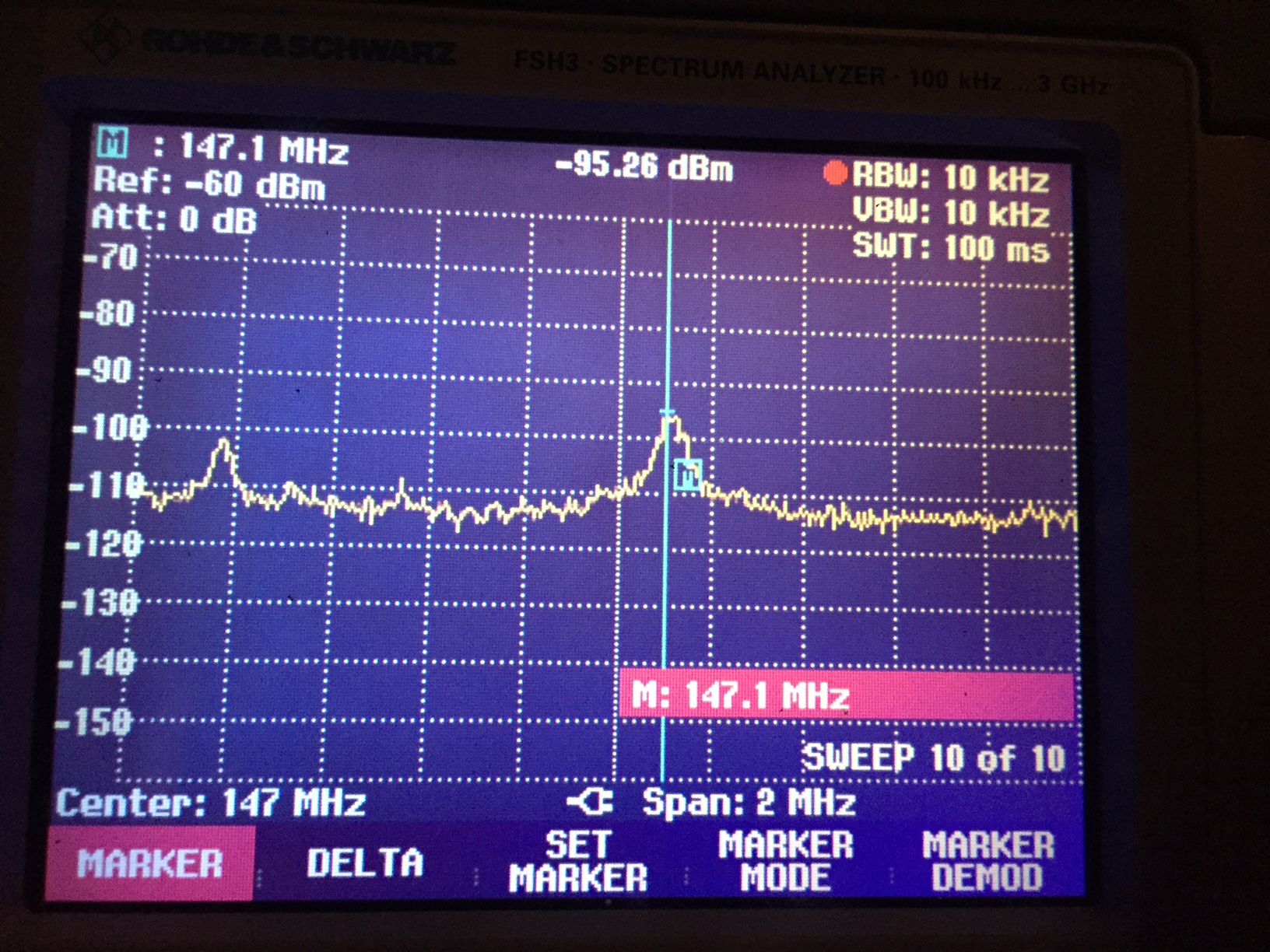
The peak interference is -95dBm, which is significantly stronger than the repeater’s -104dBm. Also note that the first image’s noise floor was around -118dBm. In the second image it never drops below -112dBm so there is at least a 6dB increase in background noise! Every 3dB is double the signal level so we have 4 times as much background noise across the board, plus an ugly spike that moves up and down as temperature changes.
Using a very small loop of wire we can “sniff” the local magnetic field and figure out exactly where it’s coming from. I got the highest level of interference when my sniffer loop was underneath the display (red wire is the loop):
Excuse the potato quality but this is the back side of the display where the sniffer loop was located. See the brown cable with the chip in it? According to the Foundation’s blog post, that’s the DPI converter chip. Below that, there are 24 data lines all pounding away with a 1.8V swing 70 million times per second. Unfortunately, some of that signal leaks out as a radio signal. We have our culprit, the noise signature with the sniffer loop matches the interference I could see on my boot-lid antenna. Despite the Foundation’s attempts to keep these signal lines as short as they could, it can still cause problems for some people (especially those running sensitive radio gear!).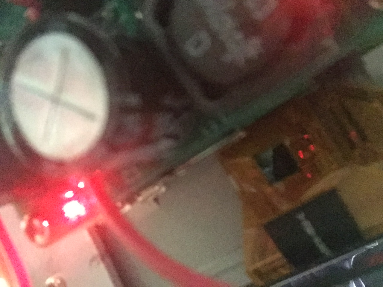
Here’s the Foundation’s official test lab plot of the touchscreen before it passed EMC approvals (now that is has passed approval, those spikes will still be there but they will be less strong):
The solution?
So, what can be done about this? Well, the Pi passes EMC certification so they have done everything they are legally required to do.
EMC testing focuses on two methods of interference transmission: conducted emissions and radiated emissions. Conducted emissions travel through wiring. Radiated emissions travel through the air. We can test for each of these and then figure out a course of action.
Test #1 – Isolate the Pi electrically
In case the emissions are conducted along the car’s electrical wiring (or chassis ground!) the first test is to make sure there is no physical (electrical) connection between the Pi and the radio or antenna. The Pi and display was powered using an isolated 5V supply, and it was separated from the metal car body as much as possible by placing it on the plastic dashboard.
Importantly, this also bypassed my RPI-CS power supply board (which uses a SMPS) to make sure that my board wasn’t contributing to the problem!
Did this fix it? Nope. So, our problem must be radiated noise not conducted.
Test #2 – Add shielding to prevent radiated interference
The Foundation’s literature admits the DPI cable is a prime candidate for causing interference, and I have confirmed that’s where the spurious signals are coming from. On order I have some adhesive copper tape which I will apply to the exposed DPI cabling in the hope that it drops the amount of radiated noise. Failing that, I can try shielding the whole back side of the display as it is possible the metal backing of the display is helping the noise to radiate. It sounds like the Foundation has already done a fair bit of work to improve the performance of the board so there is probably not much more that can be done at the circuit level.
Of course, if the front of the screen is also radiating, I am SOL. I may have to switch to an “unofficial” display that doesn’t use DPI… but let’s hope it doesn’t get to that 🙂
![]()
Pingback: Taming the rPi Touchscreen PCB | Scribblings of an Engineer