
After my last article‘s mission of discovery I set about trying to stop the rPi Official 7″ Touchscreen from interfering with my 2-way radio. It looked like the LCD ribbon cable was broadcasting spurs every ~1MHz or so right through the VHF range. I acquired some adhesive copper tape thinking I could shield the cable to prevent the noise from escaping.
The copper tape arrived, and despite wrapping the LCD ribbon cable and grounding the copper tape it failed to provide any shielding benefit. Nuts. So what else can I try?
I pulled the rPi out of my car and sat it on the bench. I told the touchscreen to stop misbehaving. When that didn’t work I got out the spectrum analyser again. I also made some smaller sniffer loops. Why pay hundreds of dollars on a beautiful calibrated probe set when I can cobble together something that looks awful but works ok, for a couple of bucks? (ok, I wish I had the real thing they look pretty awesome)
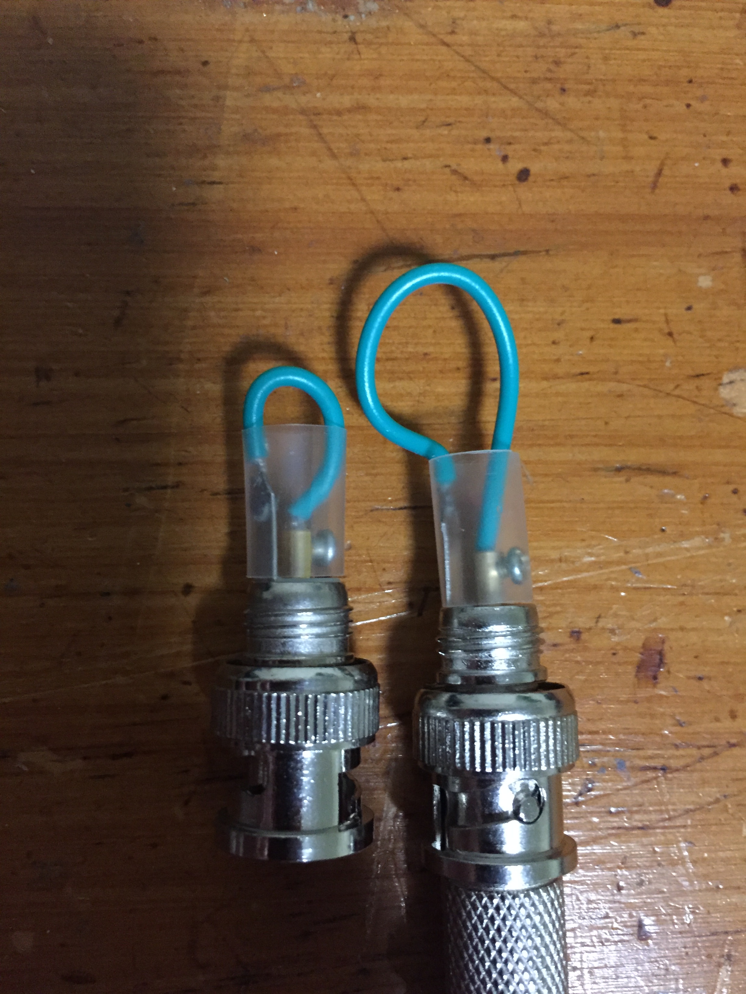
DIY sniffer loops (officially called magnetic field probes)
Since I had everything on the bench now, I also separated the rPi and the touchscreen PCBs from their mounts and spread them out on the bench. I powered the rPi via its USB plugpack.
The spectrum analyser showed that the same spurs I could see in the last article were present on the LCD ribbon cable, but they were also present on the LCD PCB itself. Aha! They seemed to be strongest near U1 and also in some nice long tracks heading off towards U3. Long tracks? Sounds like another way of saying “antenna”.
I didn’t take a photo of it but this area of the board had spurs starting at ~933kHz and then every multiple of that frequency RIGHT UP INTO THE VHF RANGE AT 145MHz. Yikes! I didn’t look to see how much higher it went… considering I’m seeing the 145th harmonic let’s just call it “unfiltered” eh?
In the pic below, these spurs were present all along the tracks indicated by the red arrows. Circled is my fix. U1 is a device of unknown heritage (it just says “TP54” on it). I suspect it may be a boost converter since it has a diode and an inductor next to it and the output of the diode is around 9V DC.
The circled fix is the addition of 2 capacitors – a 10nF and a 12pF in parallel. These capacitors go from D1’s output (~9V DC) to GND (I scratched some solder resist off the PCB to expose some ground plane). Small value ceramic capacitors are low impedance at high frequencies so I’m shorting out the high frequencies to ground.
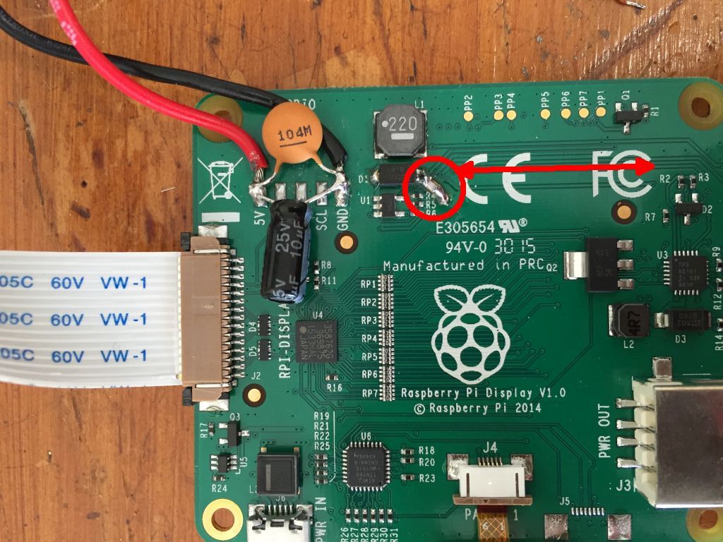
There is also another boost converter on the board: U3 is a TPS65101. The spec sheet says it operates at 1.6MHz and when I probed it, the spurs were only detectable right next to the IC (they didn’t travel far) and they were at different frequencies to the ones interfering with my radio. The “interference transmitter” is definitely U1 & D1, and the long trace. This 9V power rail seems to go to the LCD too which is why I am seeing the spurs on the ribbon cable.
So, what can a few hours and 2 grain-of-sand capacitors do?
-
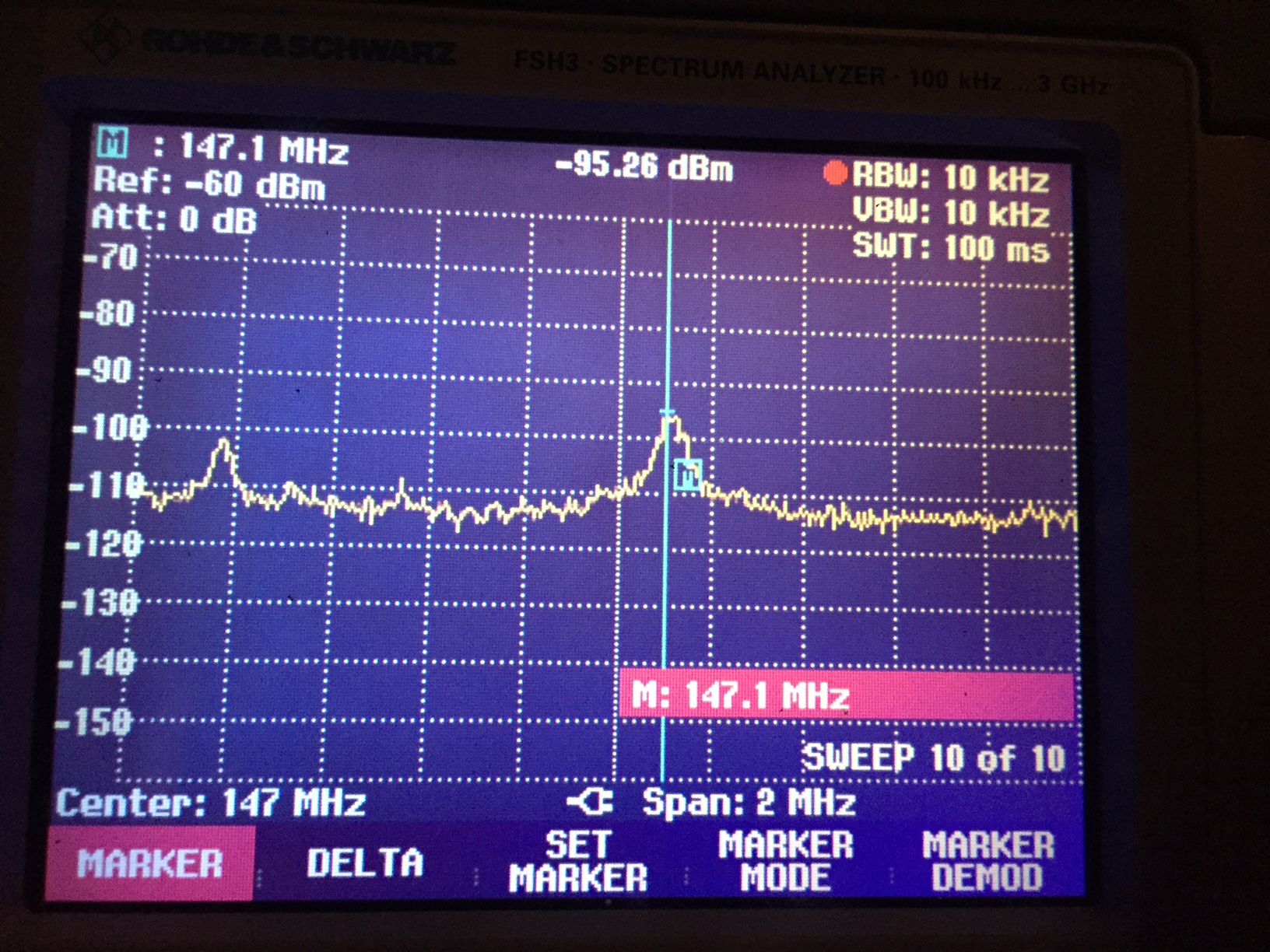
- Before mods
-
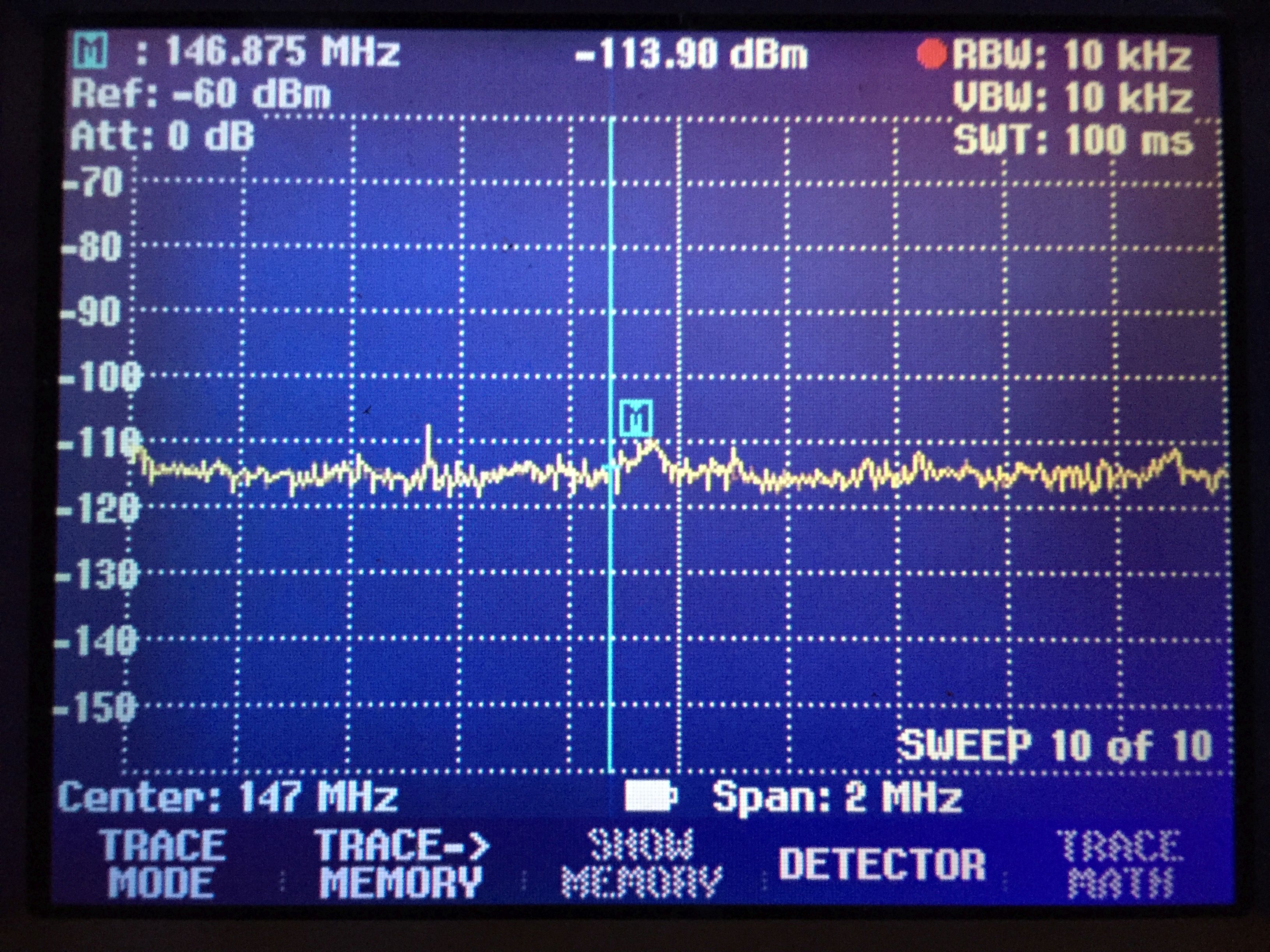
- After mods
Measured under the same conditions the spur has dropped from -95dBm to -110dBm. 15dB is a considerable difference! The overall noise floor has dropped down to -115dBm which is only a dB or two higher than with the display off. And the best news – my 2-way radio isn’t being overloaded by the Pi’s touchscreen.
![]()