I’ve had some fun over the past year with HF mobile antennas. They are an interesting challenge in miniaturisation, being quite a small fraction of a wavelength. I wanted to design and build my own to better understand how these antennas work.
While researching, I found Marty VK4KC and his brand Mad Dog Coils (Youtube). Marty has come up with an ingenious coil construction method involving threaded plastic irrigation riser pipe as a former and winding stainless steel fencing wire onto it. Tuning is accomplished using hose clamps. He openly shares all of the parts and methods required to build the coils as a DIY, and also offers pre-made coils for purchase.
Another resource I heavily referred to was of course THE site for mobile HF antennas, k0bg.com.
Overview, and Theory
I chose a 2.7m stainless steel whip as a radiator, it is sized for the old 27MHz CB band. To use this on 80-15m, the greatly shortened radiator is almost purely capacitive. A loading coil provides the opposite reactance to cancel out most of the capacitance. Near resonance, this becomes useful but the impedance is extremely low (a couple of Ohms). To match this to 50 ohms, an LC impedance match is used. A shunt inductor of around 0.5-1.0uH at the feedpoint raises the impedance to 50 Ohms.
The body of the car behaves as a (poor) counterpoise, and there are substantial ground losses in the range of 10-30 Ohms which robs the system of efficiency. Minimising these losses via proper antenna location, and bonding parts of the car together to facilitate RF current flow, will improve performance.
A surprisingly good model of an HF whip (used when bench-testing things in the shack):
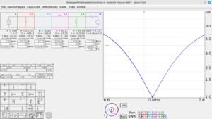
A SimSmith circuit also allowed me to understand the system better. The whip is the capacitance C1, R1 represents the ground losses (with a small contribution from radiation resistance), L2 is the loading coil, L3 is the matching coil. The matching coil should in theory be around 0.5-1uH, I have changed various values around in order to make the SWR trace a close match for my real antenna system (mostly trying to quantify realistic ground losses).
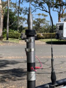
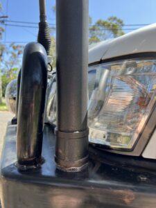
For my antenna, my idea was to have a rigid metallic mount above bullbar level. The mount will support a Mad Dog Coil (Youtube) and couple the coax shield to the rest of the car as a counterpoise. The whip will be on a spring above the loading coil.
Following Marty’s recommendations, 1.6mm x 15m of stainless fencing wire gives me enough inductance to tune from 80-15m. I used 50mm pipe, and the tuning is very sensitive. Marty VK4KC recommends using 40mm pipe instead which is easier to tune.
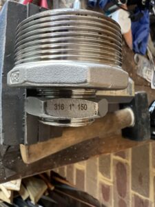
I used 316 stainless couplers and 50mm stainless pipe as an extension, to raise the loading coil away from surrounding metal. At the base, a 50mm to 32mm (2″ to 1.5″) reducer allowed the use of a step-drill bit to drill a 35mm hole in the bullbar for mounting. The 32mm size is also large enough to pass a PL-259 plug through, which makes assembly much easier.
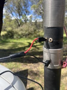
The coax runs up the inside of the reducer and stainless pipe, and terminates to banana sockets on the all-thread plastic riser pipe. The coax was cable-tied to the side of the all-thread pipe for strain relief, and foam inserted into the stainless pipe section to prevent coax movement.
The coax centre connects via wander lead to the loading coil hose-clamp, and the coax shield connects to the stainless coupler (and thence via the stainless pipe to the vehicle chassis). I have two hose clamps and leads, to allow easy band switching, so there is another open-circuited banana socket to “park” the spare lead. Band switching is achieved by swapping banana plugs. Currently it’s set up for 40m and 20m.
Protip: a liberal application of anti-seize is necessary with all stainless steel fittings, or you will have galling issues.
Self-matching weirdness
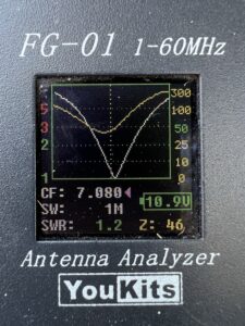
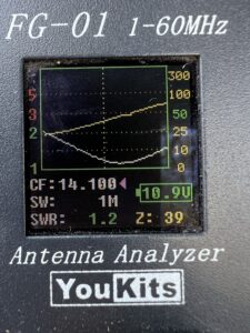
I was planning on adding the shunt-matching coil at the feedpoint, but my setup turns out to be “fortuitously matched”. This was initially a concern, because it represents a significant departure from the theory. The biggest question was how lossy this self-matching is. Subsequent on-air comparison between my antenna and a “known good” mobile station showed no difference in signal strength, so my setup is working well. I suspect the height of the riser pipe, along with the specifics and geometries of my installation, have conspired in my favour.
SWR sweeps for 40m and 20m:
Results
Signal reports with regular club contacts on 40m have been favourable, and on par with other mobile whips in the end-of-year pilgrimage. A further round of tests also showed no difference to a “known good” mobile setup. The furthest DX worked so far is a 5×6 report from an operator in Chile, on 20m. Regular interstate contacts on 40m are possible.
Other important notes
I’ve added some bonding straps between bullbar and body, and between body and bonnet, to assist with the body forming a low-impedance counterpoise per K0BG advice. In addition, my diesel injector noise was greatly suppressed by running positive and negative leads directly to the battery. If you let the power return current flow via the nearest chassis bolt, you effectively have a large loop area to pick up local interference. By running a tightly bundled cable pair, there is negligible loop area and no possibility of noise voltage injection on the power negative. There’s still some injector noise coupling in via the antenna, notably on 20m, which can be reduced by ferrites on the injector loom as well as shielding wrap grounded to the engine block.
Option for stationary operation
Using a banana-to-PL259 cable that was fortuitously hoarded for this opportunity, it’s even possible to connect an external antenna when stationary. A K1POO 40-20-15-10m OCF antenna with a dual-ferrite 4:1 Guanella balun raised the capability of the station above the ability of a shortened + loaded mobile whip. Another idea to try next time is to attach extra radials to the counterpoise socket, in order to reduce ground losses.
![]()


